This phasing antennas document shows the 80 meter band 5 elements delta loop array in use at VA2GU starting Jan 2011.
The array consists of five full size loops (300 feet of wire for each loop) erected between two 80 ft towers, spaced 300 feet; the loops are suspended on a quarter inch polyester double braid rope, running over two marine types pulleys.
Due to consistently very high winds along with up to 1 inch radial ice, a special arrangement had to be designed to support the loops' apex, allowing torsion, sway and every motion that high wires are subjected to.
Apextie.jpg shows what seems to be reliably working.
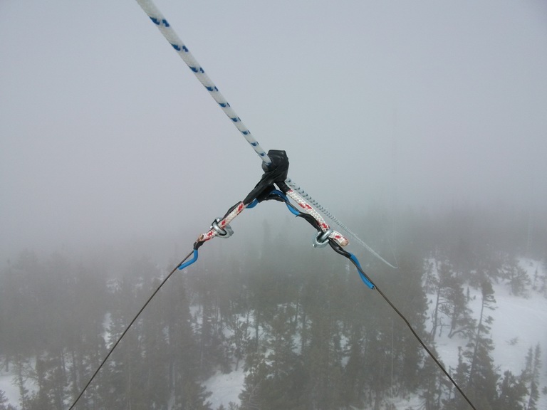
The ice problem was addressed by designing a feed system what allows running 15 amperes through each loop without affecting the phasing components; this generates the heat to prevent ice buildup.
The loop design in use is horizontaly polarized (feeding at center of the base wire). The main reason is that the array is shooting straight into that 85' vertical steel structure, with a similar interference in the back. Modeling showed significant coupling into both towers. It was easier to change the polarization to horizontal, rather than detune the towers. Besides, using TA (terrain analysis program by K6STI) and NFTA by N6BV showed that with the 18 degree slope from 1000 feet elevation to salt water 2600 feet away in beam direction, did not affect my gain/elevation angle.
Another consideration was to minimize wind drag; 14ga copperweld wire of 40% conductivity was selected. Many of you will say: "too much resistance...."
You can be excused for your ignorance (i did not say stupidity! ignorance is merely not having been exposed to the facts, or refusing to recognize them). You can refer to the excellent pdf document by N6LF:
antenna_wire_conductor.pdf, and educate yourself on the use of copperweld wire for antennas. You can click on that file, if you want to read it.
5loops.jpg is the configuration of the loops, drawn over with colors; this was necessary because this array is particularly stealth in nature except for the support rope.
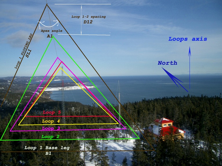
5loopsdata.jpg shows the parameters and characteristics of the array, as is presently being used for 80 meters.
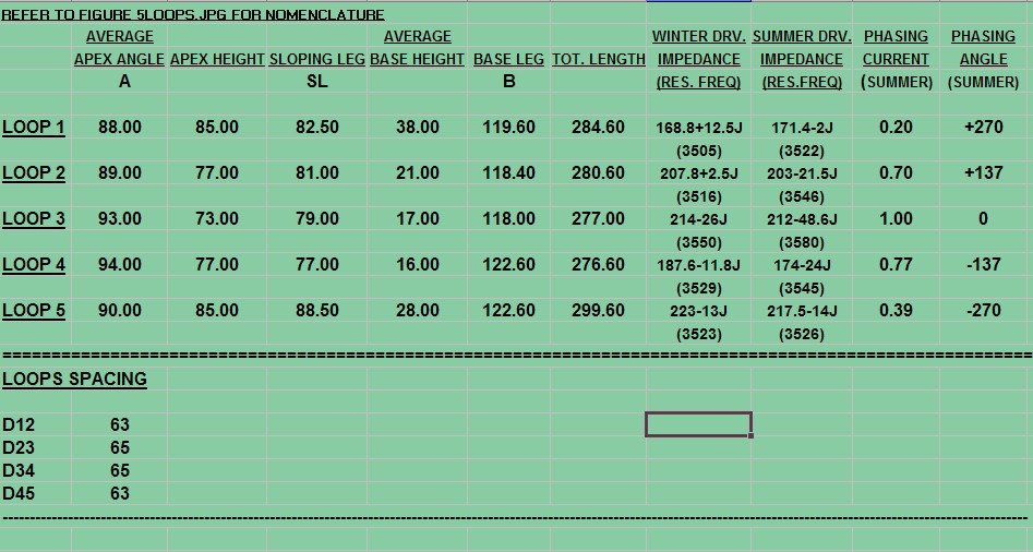
You will notice the large impedance variation between winter/snow and summer/dry rock resistivity.
This winter, i will be recalculating my values and provide a second phasing scheme.
VA2GU has developped an approach to fully design and implement the phasing of any array of antennas up to 5 elements.
The methodology involves the use of complex numbers in programs developped by VA2GU to arrive at the complex impedances of the various elements in the array. In the ten steps involved, the network components required for the proper phasing and impedance transformation to the transmitter are calculated. AND NO, I'M NOT TRYING TO SELL YOU ANYTHING; THIS IS FREE!
Refer to ANTENNAPHASING.HTM for complete details.
1998-2025 HRLabs