INTERESTED IN PUTTING UP A SINGLE DIPOLE ON FORTY, 40 FEET UP? THAT'S EASY AND MOST HAMS ALREADY HAVE THAT. DO YOU REALIZE THAT BY HANGING A COUPLE OF WIRES OFF THAT DIPOLE(NO RADIALS, NO PHASING). YOU COULD GAIN MORE THAN 7.5DBI AT 5 DEG. AND 5DBI, AT 10 DEG. ELEVATION, OVER THAT DIPOLE? THESE ARE THE ANGLES YOU NEED TO WORK "REAL" DX.
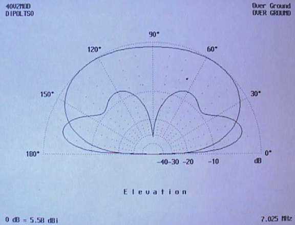
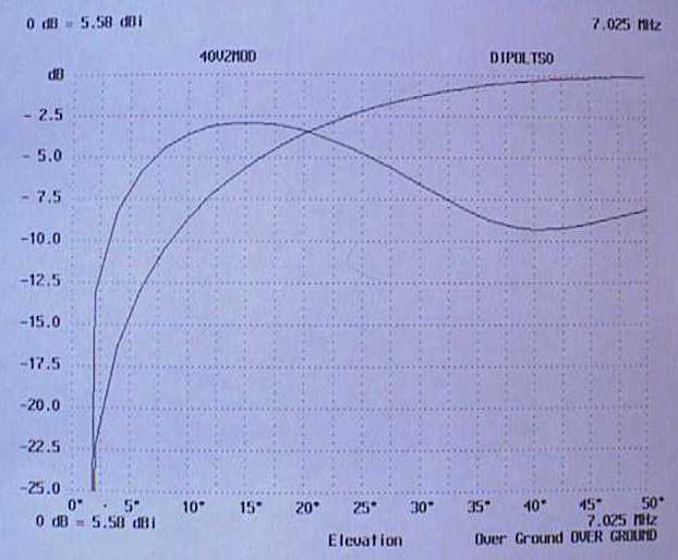
THE PLOTS BELOW SHOW AN OVERLAY OF A HALF WAVE DIPOLE AT FORTY FEET, WITH A TWO ELEMENT CVA; ON THE RIGHT, A POLAR REPRESENTATION OF THE ELEVATION CURVES. YOU CAN SEE THE CROSSOVER AT 20 DEGREES. CLICK ON THE PIX TO SEE THE FULL SIZE PLOT.
 |
 |
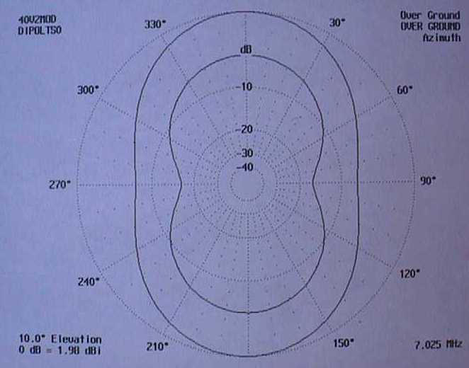
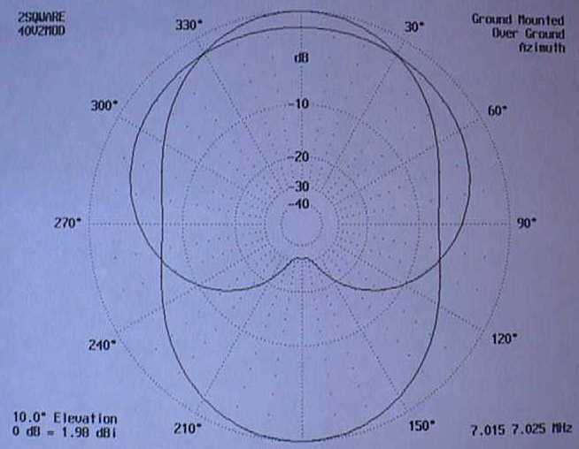
THIS ONE IS THEIR AZIMUTH AT 10 DEGREES ELEVATION; NOTE THE EXTRA 5DBI GAIN, ON THE CVA.(CLICK FOR FULL SIZE)
 |
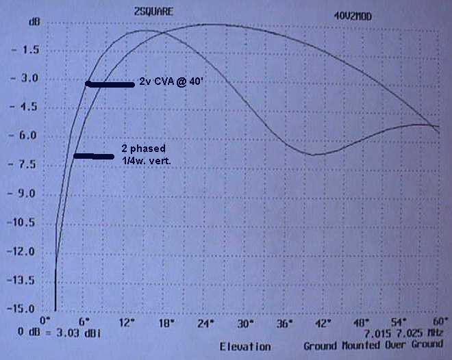
THE NEXT TWO PLOTS BELOW SHOW THE SAME TWO ELEMENTS CVA AND 2 QUARTER WAVE PHASED AND RADIALED VERTICALS (plots made using AO modeling software). AGAIN HERE, OBSERVE THE CROSSOVER AT 18 DEG ELEV; NOTE THE 2DBI GAIN AT 5 DEG OVER THE PHASED "UNIDIRECTIONAL" VERTICALS.(CLICK FOR FULL SIZE)
 |
 |
IN THE FOLLOWING TEXT, DON'T BE FOOLED BY LOW DBI NUMBERS. SIMPLY KEEP IN MIND WHAT YOUR TEST ANTENNA DOES IN REF. TO A DIPOLE OR VERTICAL. THE ONLY WAY YOU WILL GET TEN DBI GAIN ON 80METERS, IS FROM A CORNER REFLECTOR, IN A SWAMP AND REFLECTING A SIX ELEMENT CVA !!!! THIS ARRAY IS DESCRIBED IN THE HOME PAGE.
HOW ABOUT PUTTING UP A SIX VERTICAL ARRAY, OUTPERFORMING THE SIX 1/4 WAVE VERTICAL PHASED ARRAY? HOW ABOUT DOING IT IN LESS THAN TWO DAYS IN THE MIDDLE OF WINTER, BY YOURSELF AND USING ONLY A SIMPLE SWR BRIDGE, WITHOUT ANY RADIALS, PHASING LINES OR PHASING NETWORK? READ ON.
Closed Vertical Arrays (CVA) have their origin in the bobtail curtain. Reference description of the curtain can be found in the litterature; one of the best ref. is the ARRL Antenna Handbook.
The origin of the CVA however, can be found in a not so little town in western Kentucky, home to Ron (K1AO becoming K4AO now SK).
The CVA boasts four major features:
-- NO PHASING REQUIRED
-- NO RADIALS REQUIRED
-- SWR bridge only required and
-- Does not rely on ground characteristics to provide radiation peaks in the TEENS degree range EVEN ON 160 METERS.
Ron introduced the author to the CVA, in the 90's. It did not take long for an array to be blowing in the winds east of Vancouver, hanging from 120' Douglas fir trees.
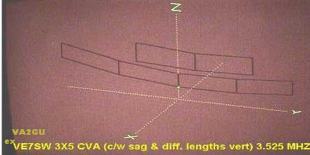
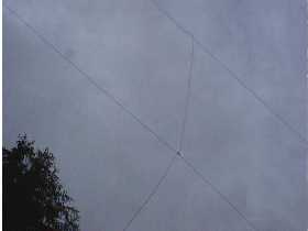
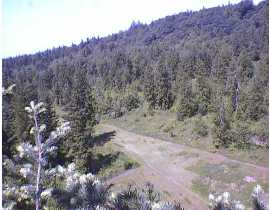
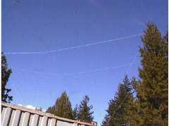 Here is what a 40m 3X3 CVA looks like. Can't see anything but nature? That's what you neighbour, nosy council member, (or your better half!!!) is supposed to see. But what's important is it works. The white lines you see, are the nylon supports for the array. Otherwise, there is nothing to see.
Those of you who knew Ron, might be aware that he did all his contacts, including DX with his CVA's at very low heights. In fact, his idea of a CVA is one on which you can work on the bottom feed point, standing on the ground: just high enough to walk under!!! But it still works extremely well. The reason is, the CVA's do not need heights to generate extremely low radiation angles.
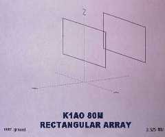
The CVA is a vertical wire array. Its basic form is a rectangle, with a rough aspect ratio of 1:2 (vertical to horizontal).
 As a rough idea, the verticals lengths end up shorter than a 1/4 wave and the horizontals shorter than 1/2 wave (e.g. on forty meters the verticals will measure around 23 feet and the horz around 46 feet). Tuning the array, simply consists of changing the verticals' lengths to get 50 ohms resistive and "nulling" out the reactance by changing the horizontals' lengths. Once an array is tuned at a given QRG and height, the verticals must be made shorter and the horz longer at lower heights, and vice-versa.
You can join side by side, as many rectangles as real estate allows, by eliminating the common vertical element. As the number of verticals are doubled, up to 3 dbi additional gain can be attained; as everyone knows, this is obtained at the expense of beamwidth.
The radiation of a given array (regardless of the number of sections used) is bidirectional and broadside (perpendicular) to its plane. Its peak radiation angle can be adjusted by varying the mounting height. This is a handy feature to use the design as a "local" (less than 3000 miles) or DX array.
Here is an example of a THREE element bi-directional CVA on forty; two heights were modeled: 30' and 75' for the top wire.
The first one hanging from two 30 foot supports, has verticals of 18.5' and total width of 100 ft (50' per horz section); this means that the bottom wire is only 11.5' off the ground!!! Its radiation peak is 3.6dbi at 24 degrees, and 2.2 dbi at 10 degrees; beamwidth is 60 degrees. These numbers can be improved by adding a parallel array,described below.
 |
For DX use, hang the array from two 75 foot supports, cut the verticals to 22.75' and span to 91.5'(45.75' per horz section); it now peaks at about the same gain (3.8dbi) but the angle has been reduced to 14 degrees; the important parameter is a ga in of over 3.3dbi at 10 degrees, and still exhibits positive gain at 5 degrees!!!! That signal will graze your lawn..... before going dx. Beamwidth has also improved to 65 degrees.
Remember, NO PHASING, NO RADIALS and DON'T CARE about GROUND CONDITIONS. |
Characteristic impedance of an array with any number of verticals, is 50 ohms; that means direct coax feed, with SWR 1:1. Bandwidth is over 125 khz at SWR 2:1, on 80 meters.
The table below shows the starting wire lengths for an array of TWO verticals, fed at the bottom of either vertical:
YOU CAN PUT YOUR ARRAY AT ANY HEIGHT THAT YOUR SUPPORTS WILL ALLOW; ONLY REQ'T IS THAT LOWER HEIGHTS THAN THE TABLES BELOW WILL MEAN SHORTER VERTICALS AND LONGER HORIZONTALS. I have put up 80 meter arrays with the top wires between 35 foot trees and the bottom wires buried in the snow in winter with no change in the impedance or SWR.
| FREQ | VERT (FT) | HORZ(FT) PER SECTION | ELEV PEAK | GAIN | HEIGHT OF TOP | NOTES |
|---|---|---|---|---|---|---|
| 1.825 | 65.5 | 205 | 18 degrees | 3.4dbi | 120 | Watch sag |
| 3.525 | 37.5 | 108.75 | 18 | 2.7 dbi | 80 | 18 ga ok |
| 7.025 | 21.5 | 52.5 | 14 | 2.7 dbi | 60 | Use 12 ga |
| 14.025 | 11 | 26.25 | 12 | 3.5 dbi | 50 | Use 12 ga |
The table below shows the starting wire lengths for an array of THREE verticals, fed at the bottom of the center vertical:
| FREQ | VERT (FT) | HORZ(FT) PER SECTION | ELEV PEAK | GAIN | GAIN/10deg | HEIGHT OF TOP | NOTES |
|---|---|---|---|---|---|---|---|
| 1.825 | 69.5 | 192 | 20 degrees | 4.8 dbi | 3.5 dbi | 120 | Sag is affecting radiation angle |
| 3.525 | 39.5 | 97 | 18 | 4 dbi | 2.7 dbi | 80 | 18 ga ok |
| 7.025 | 22.5 | 46 | 16 | 3.9 dbi | 3 dbi | 60 | Use 12ga |
| 14.025 | 11 | 23.3 | 12 | 4.3 dbi | 4 dbi | 50 | Use 12 ga |
Several software programs have entered the market and are all based on the US Navy Numerical Electromagnetic Code(NEC).These programs, developped at great costs to the taxpayer, have for the major part been made public domain (NEC-1 and NEC-2). NEC-3 and NEC-4 proviide modeling of antennas connected to ground and in the ground.
In the author's case, very large wire arrays over a multitude of ground conditions was the requirement. None of the existing programs by itself could fill the bill, contrary to published claims. But recently, Antenna Modeler, MMANA and other programs have appeared and not only run fast, but do not suffer from the previous limitations of segments and RAM resident memory.
Some of the software programs presently on the market and used by the author include:
The author started with the ELNEC program and soon ran into its limitations. AO and NWires were then tried and again petered out. This occured while running an 80m corner reflector in a marsh, with two phased verticals. Errors indicated were "too many segments" and "run time error". Later programs removed those limitations.
These programs are all great fun to run; you dont need to be a programmer or a very knowledgeable computer user to get results.They all have on-line manuals which can be printed. Most are available in other than English.
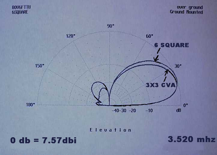
Here's an elevation/azimuth plot, generated on AO program, of a 3X3 (6 verticals) CVA on forty, with top wire at 45 feet overlaid with the plot of a 6 phased 1/4 wave verticals, remembering 4 supports rather than six, the fun to phase the six square, bury all those radials, set up elaborate switching network, phasing lines, dependency on ground conditions, etc, of the phased array.(click for full size plots)
 |
 |
 And if you are technically inclined, here is an actual current plot, for an inverted delta loop; this can be used to see how far you are from resonating your beam.
PHYSICAL CONSTRUCTION
Material and tools you need, when putting one of these arrays up.
The construction of an array is so simple, that one can be pretuned at the home QTH, lowered, coiled and reerected in less than half an hour for fielday "local" use.
First, determine the lengths from the tables above, or from your modeling software.
Then, cut the wires to the required lengths PLUS A FOOT and coil the horizontals on one spool and the verticals on a separate spool; it makes life easier when raising the array.
Wire size is not significant, unless you plan to erect a 360 feet wide, five vertical array on 80 meters (here, use 18 ga for minimum sag and 90% efficiency). Normally, use 14 ga stranded copper (RW90); it's cheap (5 cents a foot) and strong.
On larger arrays, wire size dictates the strain on the supports and the sag. You have to pull the array tight on its supports, to minimize the sag; the sag will steal from the elevation angle.
Refer to the 3X5 CVA array layout shown at the top of this page; the 5 element CVA is over 360 feet across; the whole array is suspended from a 3/16" nylon braided line (discussed below). Here, I have used AWG 14 copperweld wire. It is very light and extremely strong (also very invisible after it's up). You can also use .030 wire (AWG 20); that weighs 3#/1000 ft, but your wire loss increases by 1/3 db. Do not use welding (silicon bronze) wire; resistivity will kill all your gain.
Even with lighter wires, prominent sag will still remain on the lower wire because of the wide span. So, once you are done pruning/tuning, put as many fishing lines between the top (strong) wire/nylon line and the bottom wire as necessary. Then, you only get "mini-sags...".
SUPPORTS AND RAISING THE ARRAY
The support structures can be any point that will stand 100 lbs horizontal pull (for a 3 vert array on 40m), such as a tree top, at the 2" dia. point. Don't worry about the two ends being at the same height; I had a 2X2 (one rectangle of two verticals in parallel with another rectangle of two verticals) on 80m in VE7 land; the first array had one end at 120 feet and the other end at 90 feet.; the second array drooped from 95 feet to 70 feet. See the tuning section for notes.
 |
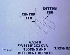 |
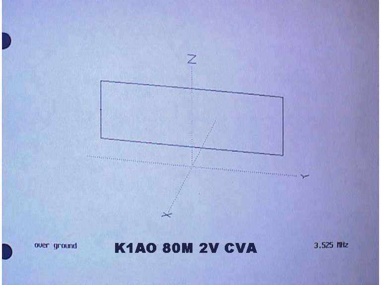
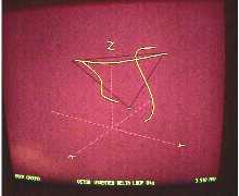
The 2X2 CVA pix on the right, is an actual "AO modeling software" screen view; data was entered in the program, with actual sags and different vertical lengths, representing the trees' heights available at the desired locations. The dimensions obtained from the program, gave a 1.1:1 swr the very first time it was raised.
Be gentle when using trees for supports; at the tie points, run a couple of 1 foot dia. loops made of #12 insulated stranded wire around the trunk; otherwise if the trunk dia at the tie point is 3" or larger, screw in a hook. This way you won't strangle the tree.
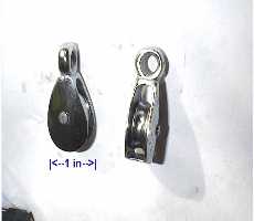
To facilitate raising/lowering the array such as when tuning/pruning, the use of pulleys threaded with a 3/16" braided nylon line supporting the system, will add years to your life..... and minimize "tuning" time. This has the added benefit of insulating the array and helps prevent unwanted "detuning" effects. You then pull as hard as your supports will permit, and the copper won't be stressed. With the use of two pulleys, you don't need counterweights. Just tie the line at a convenient point on, or near the ground.
Ron, K1AO used 2 bunjee cords, in parallel at each top end, with good success.
 |
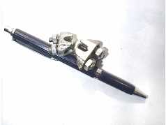 |
I've been using screw types, galvanized wire clamps to secure the insulated wire to the nylon line; use the smallest ones you can find.
The easiest way to raise the array, is to lower the top support line to working height; tie one vertical end and one horizontal end electrically and secure that to the nylon line, using a wire clamp (see pix above). Pull on the line and let the spools do their work until you come to the bottom of the first vertical.
Tie up the other horiz wire to that point, along with a length of fishing line (to square the bottom corner, after it's up). You can use another wire clamp here.
Now you should be able to make the next vertical connexion to the top wire. Do the same tie up arrangement. When you get to the last vertical, you may have to lower that nylon line end. Make sure you make the nylon line shorter than the copper wire (about 2 ft per 100 feet of wire) because the nylon will stretch, and would pull on the wire, rather than relieve it. If this occurs, you'll see the sag in the nylon line: lower the array and simply slip the wire clamp to take up the slack.
Pull on the line ends, until the feed point is raised to working height, and tie up the feedline....
To attach the feedline, run a length of fishing line in parallel to the vertical to be fed. The top of both verticals (wire and fishing line) are tied to the top horz wire; the bottom of the fishing line supports the bottom horz wire and the braid of the coax. The center conductor can then be electrically connected to the bottom of the vertical radiator.
If your array is fairly large (eg over 300 feet wide), sag can be minimized by "helping" the top supports. In this case use stronger lines at the bottom, and tie them to the support structure at a point equal to or less than the vertical length. You can then pull them tight, complelely support the lower wire and cut down on the weight hanging from the top wire.
An alternate way to relieve the sag, is to use vertical fishing lines midway between the verticals (this make it look like additional non conducting verticals).
AN IMPORTANT NOTE: WHEN SCALING TREES IN THE SUMMER, TRY TO STAY ON THE NORTH SIDE OF THE TREE (AT LEAST IN THE NORTHERN HEMISPHERE). BEES AND WASPS ALSO LIKE THESE PERCHES AND ARE NOT GOOD COMPANIONS, WHEN YOU'RE "UP A TREE..." THESE CREATURES WILL USUALLY NEST ON THE SOUTH SIDE OF TREES AND DON'T VENTURE MUCH HIGHER THAN 15 OR 20 FEET.
Since the system is 50 ohms, a standard coax or an open wire line can be used. Connect the active conductor (center wire for coax lines) to the vertical. The ground side (braid) goes to the horizontal wire, where the vertical would connect.
Tuning is accomplished through the use of a half wave section of coax, or open wire. If your array is so high that 1/2 wave won't reach the ground, then use multiples of 1/2 waves.
Make sure that the 1/2 wave length, is cut to the center QRG considered, taking into account the velocity factor (VF) of the dielectric. You usually end up with a half wave on forty being around 50 feet on 7010 khz. The RF Analyzer shown in the TUNING section below, gives you direct readings regardless of VF. Since you probably will be cutting/trying and wasting coax, use the "thinnet" coax; it is low loss, light in weight, VF of 0.73 and it's cheap (less than 10 cents a foot); so buy a 1000 feet roll and have a fielday...
If you tune your antenna to SWR 1.2 or better, then you can use any length of 50 ohms coax to reach the shack. Or if you have any other Z coax, then stick to multiples of 1/2 waves to get to the tx.
 |
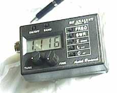 |
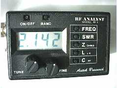
Here's where a little jewel from Autek Research can make your life easy. Their RF Analyzer is actually a microprocessor based signal generator; two models cover from 1.2 to 500 mhz. I use the HF unit for 160m through 10 meters. It fits in your shirt pocke t, has an LCD display, is housed in an ABS case and gives you QRG, SWR, Z, L and C. With a simple formula you derive actual R and X. The manual supplied with each unit, will make an instant tech. of you. The only thing i don't like with the unit, is it's so small I slip it in my shirt pocket. By doing so, the unique toggles switches sometimes actuate the power. Although it will turn itself off after about 15 minutes (can be disabled), I resorted to cut off the toggle flush with the unit. Presto! problem solved.
You'll find an ad in any month of QST magazine for that unit. It is powered by a single 9v battery. I use the rechargeable kind and it runs long enough to tune a whole array. The unit has been in production for at least five years, is made in Madeira Beach, Florida and has a one year warranty. You see the UHF connector on the pix; don't let it fool you. The unit can be used with any feeder Z. It sells for a little over $100. US.
Don't buy the unit made by MFJ. Sure it works, but....it's bulky (more than three times the size of Autek's), has swinging mechanical needles, uses more than half dozen AA batteries and costs twice as much.
If you don't want to spend the 100 bucks for the analyzer, a noise generator or even a simple SWR bridge will do fine. The only thing you sacrifice if you are not tuned to less than 1.3:1, is front to back. For SWR up to 2:1, gain variation is less than 5% of max.
Tuning is accomplished through the use of half wave section (or multiples of 1/2 wave) of coax or open wire discussed in the FEEDLINE section above.
The array can be fed an any point of any of the verticals. However, for best balance and ease of tuning, feed an array with an even number of verticals, at the center or bottom of any of the verticals. Odd numbered vertical arrays are best fed (for balance) at the center point of the center vertical, ONLY if your feeder can leave the array at right angle for at least 1/8 wavelength. If your setup cannot accommodate this, don't try to tune the array; the electromagnetic pick-up on the feedline will generate circulating currents, and give you false swr/z readings. You can put a current choke at either end of the 1/2 wave feedline to cut down those effects, but it may not be sufficient; it is best to feed that vertical at its bottom. The feedline can then drop straight to the ground and eliminate the pick up.
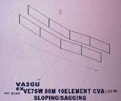
If you use trees of different heights because they are at the right place but want to minimize the elevation angle, put each array as far up the tree you care to climb to and cut the verticals to different lengths. This arrangement will result in a sloping CVA, as seen on the pix at the top of this page; don't worry. It might "look" funny (if you can see it...), but the performance will be the same as a CVA mounted at the average height.
What lengths of wire, you ask? This is where you use the bridge or preferably the analyzer. The vertical dimensions are not critical, as long as you can tune the array to better than 1.3. But keep in mind that when you shorten the verticals, the horizontals must pay the price (horz must be made longer, by roughly twice what was cut off the verticals) There are optimum dimensions for gain and f/b. A good starting point is shown in the tables above.
 |
 |
When additional gain and/or front to back rejection is desired, a second array, parallel to the first one can be raised. But remember that the additional gain is provided at the expense of beamwidth. So make sure you are pointing to the right azimuth!!!! The "driven" array become the director and the other one is reflecting.
This second array need not have the same number elements as the first one, nor does it need to be raised to the same height, or be "in line" with the first one(this "squewing" or offset, starts shifting the radiation pattern when you get to be offset by 1/4 to 1/3 square off center); the foregoing does not seem to affect gain or f/b.
If your supports are separated by more than the desired spacing for optimum gain and f/b, use nylon lines between both arrays to pull them to proper distance. For 80 meters, a separation of between 55 and 65 feet is optimum. For 40 meters, 28 to 33 feet works well. For 20m, use 14 to 17 feet. As you can see, this is quite predictable, but gain and f/b will start to deteriorate beyond these values.
To tune the second array, make sure you bring array #1 DOWN TO THE GROUND; otherwise you will get erroneous readings due to mutual coupling. Tune #2, then raise #1 and voila!! you got yourself an extra 3dbi gain. If you were careful enough to tune EACH ARRAY INDEPENDENTLY to SWR 1.1, then raising #2 will not affect the Z and SWR of #1.
You now have two coax ends, hopefully reaching the ground....You can take these two ends to the shack, or put a NON-SHORTING coax switch there and feed the 2 arrays with one feedline. I have been using Potter and Brumfield latching relays to do that function, and it works well to 14mhz. Use the 12 or 24vdc variety; no power is required to keep the contacts in either position. The 12vdc is handy, as you can use a 9v battery to do the switching. Besides they are only 20 bucks each.
Do not waste your time putting up a third array; it's won't "light up".
Now, since you will be really impressed by the CVA performances, you will want to put at least one array up for each band. This is where it gets easier. Since you have now climbed all those trees and set up pulleys/nylon support lines, everything is ready to receive the CVA for the other bands.
In fact, the nylon support line of a 2 vertical 80m CVA, will provide the top support for a 3 vertical 40m CVA, and a 3 vertical, or 6 vertical 20m CVA. The only rule to follow is to space any vertical by 3 feet or more from its neighbour, to eliminate coupling. Same goes if you erect the array from a steel structure. Keep the closest vert wire 3 feet or more from it. DO NOT WORRY ABOUT THE TREES; MY ARRAYS ARE ALL ERECTED AMONG ALL KIND OF LEAF/EVERGREEN TREES WITHOUT ANY PROBLEM.
I have been using different feedlines for each array; you may be able to use a common feedline in these nesting cases, but i never tried it. Coax is cheap! It has been noted however, that even if the other CVAs are in a harmonic relationship, they practically do not interact when nested.
Nesting parallel arrays is impractical, since the separation between parallel arrays will be different for each band. Refer to Adding Parallel Array above for dimensions.
(updated 250104)