The bulleted list below, targets specific arrays to get you directly to the topic you want. Simply click on the related name.
Some links are not active yet .
| |
 |
 |
PREEMPTIVE NOTE:
APRIL 2005 VE7SW HAS MOVED TO A MOUNTAIN SITE OVERLOOKING THE ST. LAWRENCE RIVER IN QUEBEC, AND HAS CHANGED THE CALL TO VA2GU. THE ONE MILE ROAD TO THE MOUNTAIN TOP HAS BEEN COMPLETED AND SUMMER 2006 WILL SEE THE BEGINNING OF A PIECE EN PIECE LOG CONSTRUCTION; SINCE I CANT WAIT FOR THE FINISHED HOUSE, A SMALL ACCOMMODATION NEXT SPRING WILL ALLOW IMMEDIATE OPERATION FROM THE TOP.
2007 UPDATE:
VA2GU IS NOW PARTLY OPERATIONAL FROM THE TOP , WITH LIMITED ANTENNA CAPABILITY (80M DIPOLE HUNG BETWEEN TWO PINES AT 8M ABOVE THE ROCKY TOP). SIGNALS ARE JUST ....WHAT THEY SHOULD BE, THAT IS YOU HEAR EVERYTHING AND THE NOISE IS NIL (S4 WITH 90DB OF PREAMP FROM HB TR SWITCH + PRE-AMP ON THE K2).
HAVE ALREADY WORKED JA, VK, 9V1, ETC, ON 80M CW BOTH LP AND SP. (I DO NOT OWN A MIKE AND THE K2 DOES NOT HAVE THE SSB OPTION)
MY MAIN OBJECTIVE IN MOVING FROM VE7 LAND WAS TO WORK DX 24/7 365 DAYS OF THE YEAR.
SOME (ALL?) OF YOU WILL LAUGH, BUT THAT WONT DETER MY RESOLVE.
SIGNALS HAVE STARTED COMING IN AT 11AM SINCE I STARTED LISTENING BEGIN NOV '07 AND I HAVE BEEN ABLE TO WORK EU FROM NOON ON SINCE THEN. THE DAYS I DONT HEAR SIGNALS SEEM TO BE MOREDUE TO THE LACK OF STATIONS RATHER THAN SIGNALS NOT COMING THROUGH.
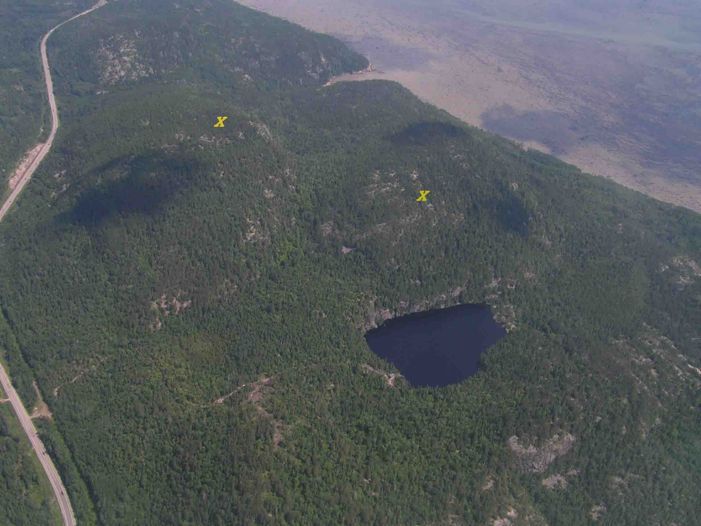
I HAVE STRUNG A 2000 FOOT POLY LINE BETWEEN THE TWO 300M TOPS ON THE PROPERTY (THE YELLOW Xs ON THE AERIAL ABOVE); THIS HANGS AN AVERAGE OF 275 FEET ABOVE THE VALLEY BELOW.
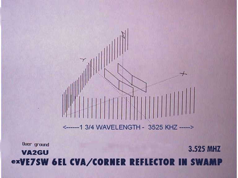
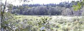
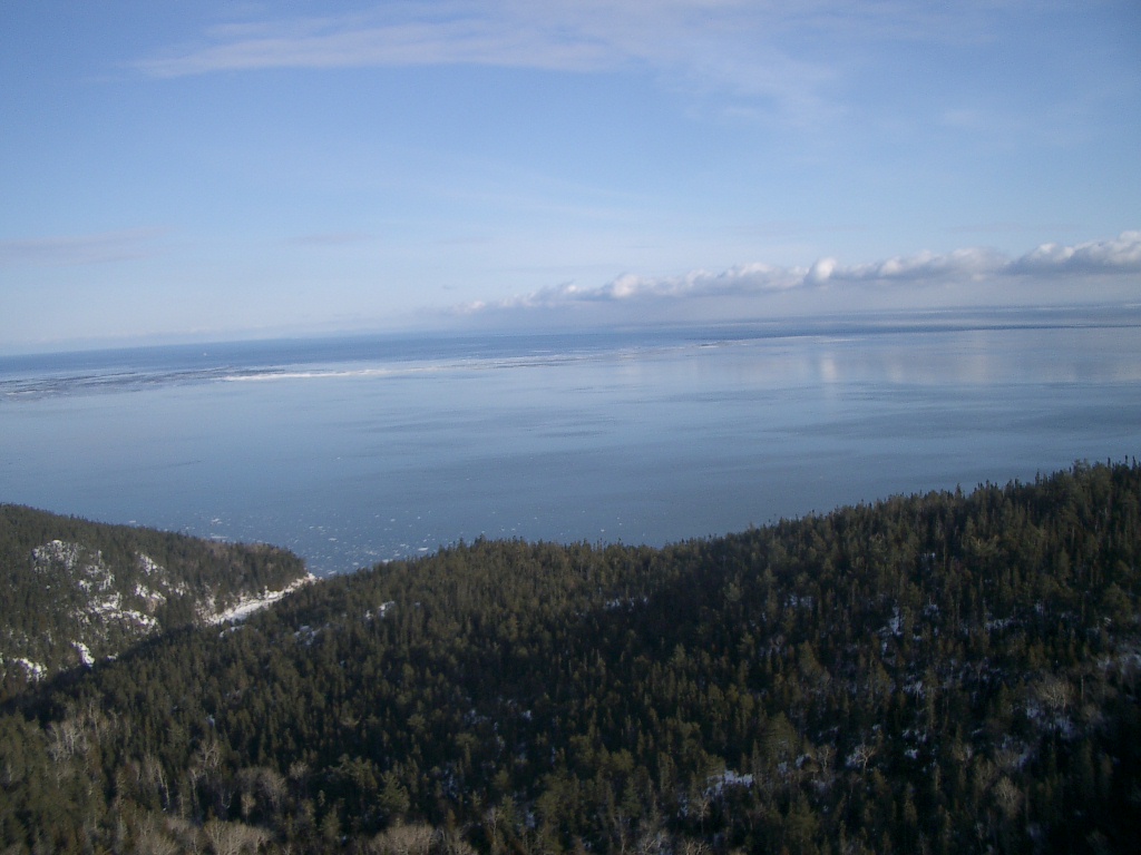
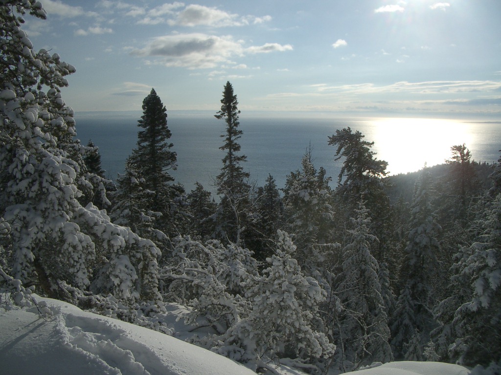
AM IN THE PROCESS OF RUNNING THE 1500 FEET OF HB O/W LINE TO THE VALLEY AND WILL HANG A 3 EL PHASED 80M CVA FROM IT THIS WINTER/SPRING. BELOW LEFT IS WHAT THIS CVA WILL SEE. BELOW RIGHT IS VIEW FROM OUTSIDE OF SHACK TO VK/ZL LP (120 DEGREES HERE).
NEXT SUMMER (2008) WILL ALSO SEE FINISHING THE HB LOG HOUSE (NOW CLOSED FOR WINTER) AND ERECTING TWO 80' TOWERS. THESE WILL HAVE 275' SEPARATION AND WILL SUPPORT A 3 EL PHASED CVA FOR 80M AND A 1/2 WAVE 160M DIPOLE . THIS 3 EL CVA WILL BE PHASED WITH ANOTHER 3 EL CVA 55' AWAY, HUNG LOW BETWEEN TREES FOR AN EXTRA 3DB GAIN AT 120/300 DEGREES. HANDY, THAT CVA's DO NOT NEED RADIALS.
THE AERIAL VIEW ABOVE SHOWS THE PROPERTY BEWTEEN THE ROAD AND THE SEA WATER (ST LAWRENCE RIVER) AND THE TWO HILLTOPS WHERE I HUNG THE LINE IN A DIRECT N/S ORIENTATION.
THE WINDS ARE REAL AND TREES ALL SLOPE TO THE N/E AND HAVE VERY FEW BRANCHES ON THE SW SIDE!!!
125 YEAR OLD PINES ARE 35 FEET TALL AND HAVE A TRUNK DIA OF LESS THAN 12 INCHES. VE7 TREES ARE THEN 150 FEET TALL AND 36 INCHES DIA.....OR MORE.
I LIKE TO OPERATE CW AT A GOOD CLIP AND PREFER TO RAG CHEW RATHER THAN RST/73/CUL.
(ZL4GU, WHERE ARE YOU?).
IF YOU CALL CQ ON 80M CW AT 1800Z OR BEFORE, BEAM NORTH AMERICA; CHANCES ARE I'M ANSWERING.
The information presented in these pages, is a result of the author's experiences; if some statements offend particular equipment/software manufacturer, it was not intended so. However in my experience, the recommended material has been chosen to be more friendly in its uses. As new upgrades become available, these recommendations may change, and the author welcomes your suggestions. As time permits, the pages will be updated.
This site is still in its infancy stages. Some of the links may not connect yet. Thanks for bearing with the construction phase.
This home page is the result of several years of tree scaling, blisters, cuts and bruises caused by hoisting arrays in all kinds of "natural" environments.
One of the reason to publish these pages, is to provide some information for those who enjoy free range (antenna farms), and don't fear to tread where eagles dare!!! BUT stick around... small spaces can also enjoy big performances; refer to the CVA page
Present day litterature, seem to concentrate on pea sized yards with no structure to support the wires. The author had to extrapolate on the existing material, to arrive at practical considerations on the building and use of highly efficient wire arrays.
However, many of the wire arrays presented here, and in particular the CVA, requires very little in terms of time, material, expenditures and both, vertical and horizontal real estate.
An additional benefit of wire arrays, is their stealth nature. If you have nosy neighbours or local suspicious council members, these arrays will avoid visual detection; this can be a disadvantage when you want to see if your array is still up...; usually the feedline is there, seemingly hanging from a "sky hook".
For those of you using the earlier generations of computers, I have limited the pictures on this first page to accelerate its loading on your browser. On subsequent pages, the pix are of lower definition; but a click on most of these will bring up the full screen version.
TOP OF PAGE
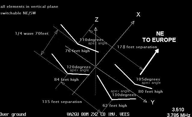
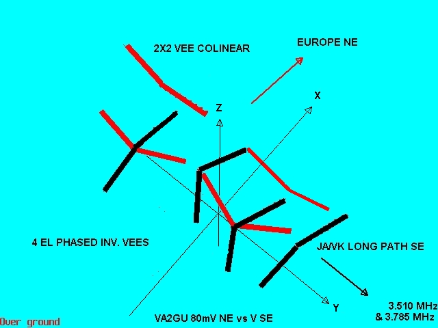
Delta loops plagued by freezing rain, have been replaced by these colinear inverted vees .
The intent is to lessen the vertical loads of ice loaded horizontal wires, by replacing them with sloped wires of inverted vees. 2 of these 4 elements use 2 of the existing supports of the 4 elements vee beam to JA/VK.
This new monster wire array has just been completed, phased and PA matched.
You will note that the array is unlike the existing 4el vee beam, in more than the actual layout, besides their basic structure i.e. colinear vs in line vees.
The colinear elements have been laid out almost vertical, as opposed to the beam.
The main reason for the vertical elements is strickly its geographical orientation and the weather.
Being 90 degrees to arriving NE freezing rain from the gulf of St. Lawrence river, they gather incoming humidity, which evaporates on the wires; this creates a cooling effect, just enough to lower the temperature to below freezing. You get the idea! The beam is further away from the slope to the river and tend to accumulate less ice. This is noted on the 3 el. phased vee beam for CW, located 300 feet further south from these 2 beams. These 3 elements have rarely seen any ice accumulation (a min. amount of few mm, once in last 10 years).
Lots of trees/towers scaling, tree branches grabbing of the #12ga (2.1mm) copperweld wires to tune each element to between 3500 and 3520kc.
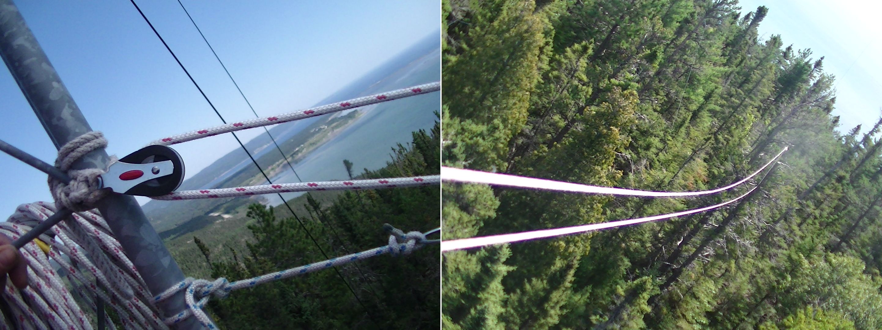
In the process, i have found some easier ways to tune antennas, when fighting tree branches; they tend to grab the copperweld "coils" when lowering the ends to tune to proper qrg; one shortcut way of avoiding these branches interferences is to put up a clothes line between a high point and a spot on the tower that will clear the tree tops when lowering/raising the ends for pruning.
I use a one wave rg58 coax to my VNA (or u can use an Autek or MFJ) to verify the impedance each time I prune the element. A rough idea for tuning wire elements,is to use the 492/f for lengths. I actually now use 2kc change per inch pruning and usually do not cut the wire right away; just fold it back over the end and twist it till you done tuning.
As you very well know, balanced antennas fed with unbalanced lines (coax, hardline...), will show very high susceptibility to ground currents riding on the outside of the feedlines' shields and will screw up your readings, matching, etc. Some prefer to use toroids (may be affected by moisture, costs money, etc). I have always used successfully a hand RANDOM wound choke made up of 8 turns, 8 in dia (approx 20 feet long) coil. I never use foam type coax, as the center conductor will migrate towards the shield and short out (as Boeing found out on their planes, in the sixties). Good old RG213 or RG8 with polyethylene dielectric does the trick. You can see if your choke is inductive enough, by monitoring your impedance while grabbing the coax; if the readings change, add a few more turns.
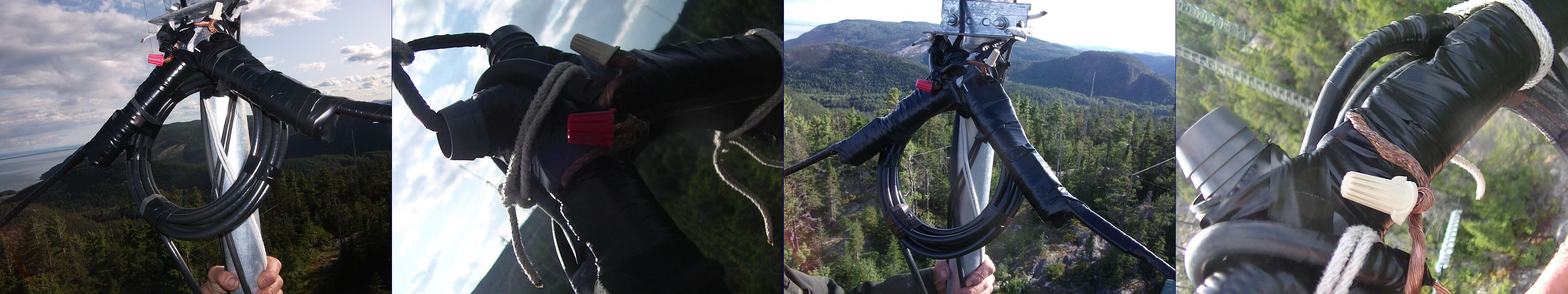
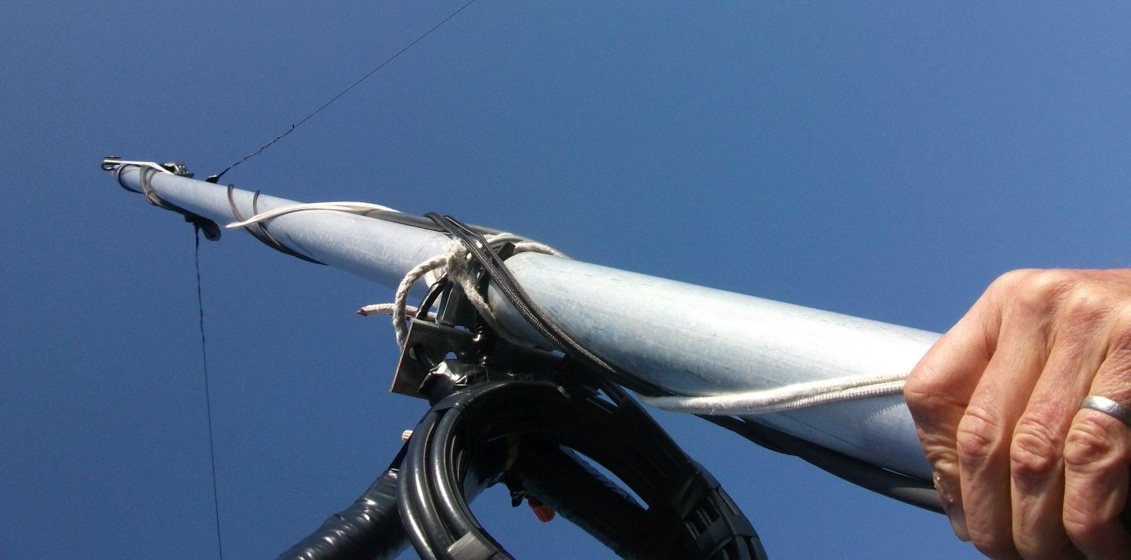
I have also started to use marrettes for the junction coax-antenna as seen below. It is not affected by rain, snow or ice and can be disconnected if desired. No special tools needed here. Take care to leave a long enough uncoiled end to loop over and down the coil, for antenna connexion. Prevents the moisture from running down the open shield.
Using copperweld (min 40% copper), can be tricky for connections, if the copper has oxydized. If so, run a fine emery cloth to "brighten" the copper and put solder on the copperweld wire for a length of 2 feet, on the ends where the feedline is to connect. I then solder a 7in length of coax shield, at the "proper" place (see below).
Past few aerials have used a PVC "+"; 2 of the legs run with the half elements, which can be drilled into each leg to support the antenna. The 2 other PVC legs will be used to secure the apex to your mast. Wrap the copperweld end over itself, beyond the "+" end and solder that piece of shield, close to where you are to marrette the antenna. This can be assembled in the shack, before erecting the antenna.
On the picture below, you can probably see a sort of mass beyond the "+" ends. This is a "wind relief", to smooth out the transition PVC-copperweld, so it does not fatigue when the winds blow. I have actually used a one foot piece of coax, wrapping it with stretch tape and black tape over the "+" and the copperweld. I finish the job by wrapping the whole assembly with that stretching tape and finish with black tape.
DO YOUR TUNING OF ALL ELEMENTS IN SIMILAR WEATHER CONDX. When you tune arrays of several elements having in view of phasing them, it is important to do your tuning of ALL antennas at relatively same weather; i.e. rainy/foggy or dry summer days, windy days, etc. The impedance varies wildly (at least on this granite rock) by as much as 30kc for wet vs dry days. These impedances are critical to obtain the proper L/C values, dictating the correct phases and currents of your project.
The colinear array is directed to beam to Europe to the north east from here and can be switched for SW direction; it has 2 elements to the north in the same plane, i.e. they are in line with each other,
end to end and are labeled NW and NE.
The other 2 elements are 1/4wave spaced (70feet) to the south, are also colinear to each other and are labeled SW and SE.
The spacing is not critical and can be set as low as 1/8 wave to suit your qth. Front to back (F/B) and gain will be swapped when you narrow the spacing, i.e. more F/B at narrower spacing and vice-versa, as well as affecting your bandwidth (less at 1/8w).
TOP OF PAGE
I cut the feedlines (hardline, rg8 and rg213 coax) for the NW, NE, SW AND SE elements for 3.5mc.
NW ONE WAVE 3540KC RG8, 182feet at 0.67 VF
NE ONE WAVE 3525KC mix of hardline 106ft (vf 0.9) plus RG213 175ft (vf 0.66)
SW ONE WAVE 3512KC RG213 187feet at vf 0.75
SE ONE WAVE 3510KC RG213 187.5feet at vf 0.75
I cut all antenna wires to start at 492/qrg, i.e. 140ft and fold over 2 extra feet at the ends. I use copperweld, 12ga, (2.1mm) min. 40% copper.
The final lengths, impedances and resonant frequencies for the colinear elements for 3.5mc are as follows: it will be noted that each half do not have to be the same length (and are actually not, here on the NE and SW halves); may save you frustrations in trying to be perfect. The pattern will not be affected appreciably, until you get to 20% difference between the halves!
NW 137'8" with equal west and east ends at 68'10"
NE 135'6" with the west end at 68' and the east end at 67'6"
SW 137'11", with the west end at 69'5" and the east end at 68'6"
SE 133 feet with equal west and east ends at 66'6"
resonating at:
NW 3480KC 53.3+0J
NE 3513KC 51.4+0J
SW 3527KC 79.5+0J
SE 3496KC 75.8+0J
YOU WILL NOTE THAT IF YOU RAISE/LOWER THE VEE'S ENDS, BY AS LITTLE AS TIGHTENING THE ENDS' SUPPORT LINES BY ONLY A FEW INCHES, THUS RAISING THE ENDS BY 2 TO 3 FEET, WILL CHANGE THE RESONANT QRG OF YOUR VEE. I.E. RAISE ENDS = LOWER THE QRG, because of less capacitive coupling between the antenna and the ground.
These variations between lengths and resonant qrg of the north and south arrays, can be explained by the electromagnetic heights as seen by the antenna (the physical heights of each antenna, coupled with the ground conditions below (resistivity, soil conditions, trees, buildings, etc). These factors will produce an ACTUAL antenna height and thus ACTUAL impedances that must be used for phasing.
As noted above, i was lucky enough to have very close impedances for the 2 elements of the north array (NW and NE), as well as similar impedances for the 2 south elements (SW AND SE).
This allowed me to just short out the 2 north elements with a simple UHF Tee and the 2 south elements with another Tee.
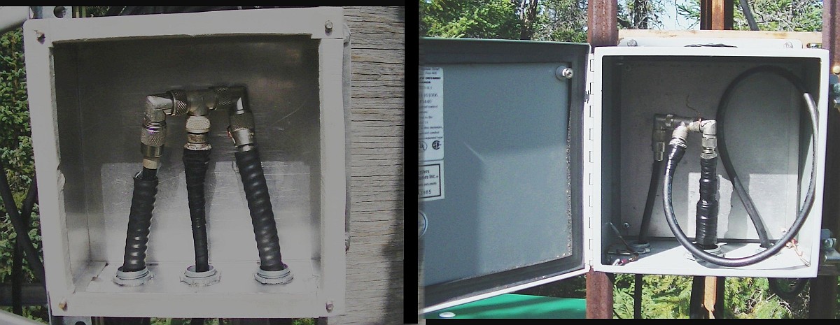
Then i know that the current distribution will be shared equally. If this had not been the case you can still short the 2 elements together, but the currents and phases in each element will be different, with the result of squewing your pattern towards the larger current's elements.
This may be handy if your supporting structures are not oriented towards the desired direction!
When this inequality happens and you desire to have equal currents/phases, you have to insert proper phasing components (L and C).
However, arrays having to phase each element separately as I did in the 4el vee beam, would not allow you to short them together, even if the impedances are identical. The reason being that you want different and very particular phases and currents for each element. Doing so, each element contributes to the gain of the array. These values can be obtained by using the 10 steps of VA2GU ARRAY PHASING software and .xls spreadsheet (available for free on this web site HRLABS.NET)for the phasing of up to 5 elements.
The colinears are located 50 and 120 feet from the shack. I tuned 2 one wavelength coax (rg213) from the tees to the shack; i got 3520kc one wave for the north colinears to the shack and 3510 one wave for the south colinear array.
The Array Solution's VNA2180 little jewel, was custom calibrated; this feature allows you to measure the impedances in the shack (feedline end), as if you were right at tee junctions outside.
The north array measured 27+0j at 3510, with the south array 38+0j at 3500kc.
I put in my current probes (one wave rg58 + 3/8in dia, type 43 ferrite material 10 turns 26ga) into each tee and into each of the elements.
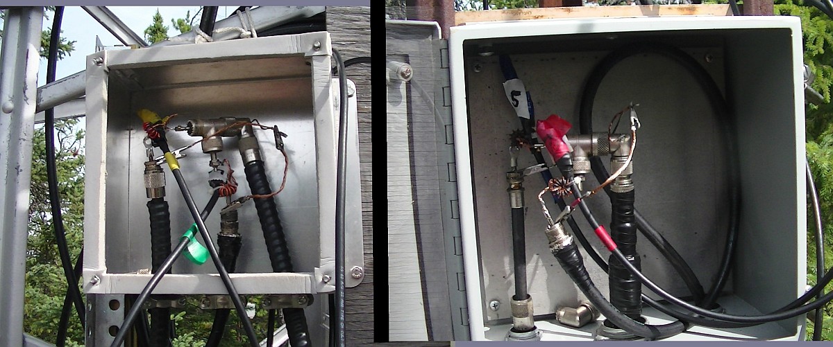
I then feed both feedlines into a phasing box in the shack and connect the 2 feedlines using the proper length of coax to get the desired (modeled) phase angles and currents for 3.5 mc and beaming NE.
MODELED: ACTUAL REALIZED:
South colinear at 0 degree and 1amp current South colinear 1.0amp at 0 degree
North colinear at -140 degrees and 1 amp current. North colinear 1.0amp at -144 degrees
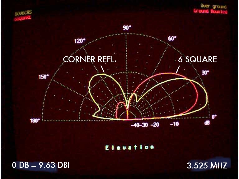
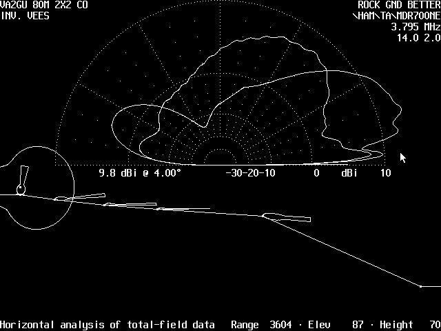
A theoretical gain of -4db/4*, 7.2db/20* and 10.2db/42* with a f/b of 7.2db (combined horizontal and vertical polarizations) was obtained via modeling with K6STI's NEC WIRES (NW) without taking into account this qth's topography. The poor f/b was intentionnally used, in order to maximize forward gain, as rear interference is not a concern at this location.
Although a 4 degree elevation is useless for europe, it important to note that a "gain" of -4db is realized with this array on flat terrain.
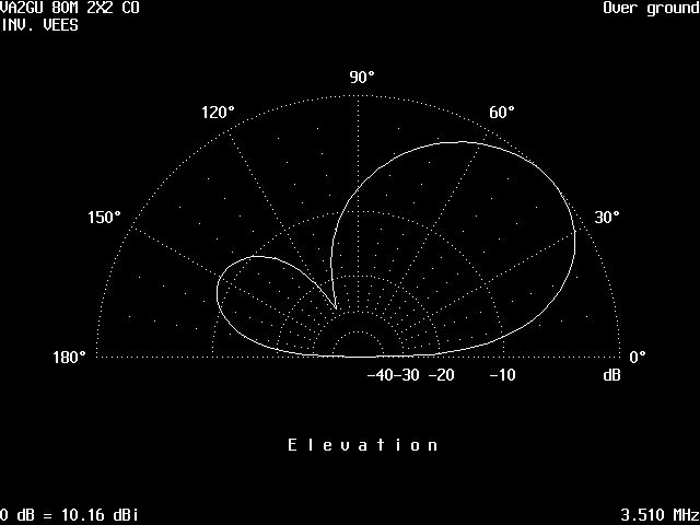
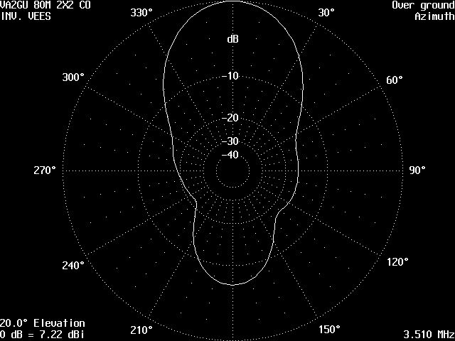
80CO22VEL.JPG 80CO22VAZ.JPG
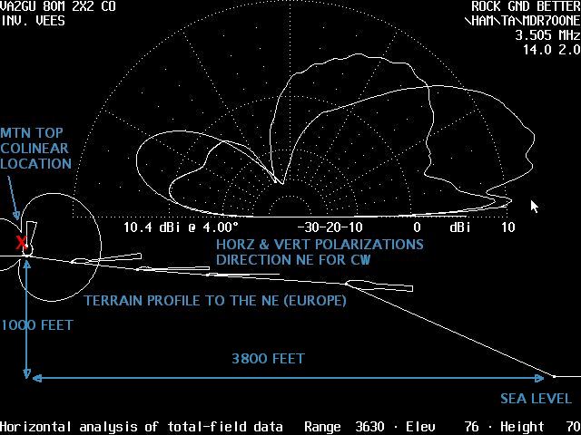
When you factor in this qth's height (1000ft ASL), slope (ave 14degrees) and proximity to sea water (3800
feet), using K6STI's TERRAIN ANALYSIS (TA) program, the following gains are realized, with the patterns below.
10.4db/4degrees horz. polar , 9.0db/4degrees vert polar and
13db horz, 3db vert/20degrees, 8db horz & vert/42degrees.
This clearly shows how much a slope favors the low elevations to the detriment of the higher angles.
You will also note that this NE slope is not ideal for JA/VK long path, it shows nevertheless a gain of 5db/4degrees, making it a difference of 9db, only due to the terrain profile.
However, the useful 20 and 40 degrees Europe NE gains are substantial at 6db/20 and negligible at 40 degrees.
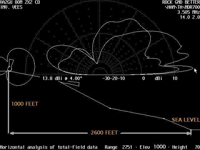
The 3 patterns below show how much the gains/elevation angles are affected by the presence of different types of terrains: flat and 2 types of slopes. You will note that even a small change in the slopes (NE and SE) produces a large difference, mostly at the lower angles.
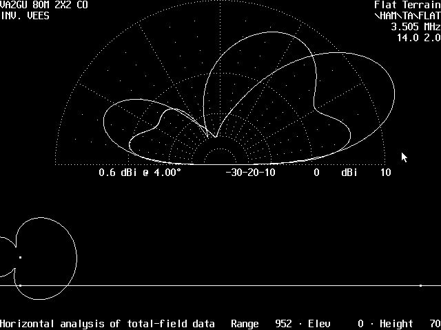
FLAT TERRAIN NE SLOPE SE SLOPE
The above picture shows the overlapped pattern of the vertical and horizontal polarizations of the array, as
well as the terrain slope (the antenna is at the dot on the left on top and sea water is bottom right).
This qth's elevation and slope favorizes horizontal (greater gain and lower elevation angle), over vertical.
The foregoing is in agreement with VA2GU's antennas experiments at previous qths, as well as with the numerous publications on the effects of qth's height, slope and sea water proximity on a signal (ON4UN'S LOW BAND DXING, N6BV'S, etc).
Reversing the north and south colinears, beaming south west
north colinear 0.97amp at 0 degree and
south colinear at 1.0amp at -148degrees producing a modeled/calculated gain of
-6db/4degrees, 7.24db/20* and 10.13db/42* with a f/b of 7.0db was obtained via modeling with K6STI's
NEC WIRES (NW) without taking into account this qth's topography
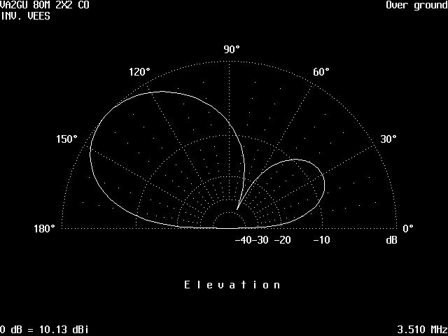
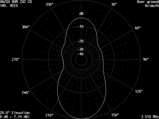
80CO22ES 80CO22AS
When you factor in this qth's height, slope and topography, a subtantantial gain is realized.
This qth's south west direction is not blessed by the same topography as to the south east JA long path
direction, or even the north east. However it still benefits from a 19* slope, but over a shorter distance (1100feet horizontal).
A large lake at that distance and 400 feet below the top "just happens" to be in line with the colinear's
south west radiation. The path then goes over rocky mountain forest and does not rise above this mountain top for more than 4 miles, at less than 500 feet higher.
By then the pattern has stabilized to the following gains over correspondingly flat terrain, as obtained using
K6STI's TERRAIN ANALYSIS (TA) program.
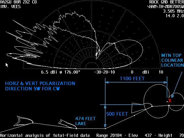
MDR35SW
6.5db/4degrees, 12.8db/8degrees and 13db/20degrees horz. polar
7.3db/4degrees, 10db/8degrees and 7db/20degrees vert polar
You will note that the gains are quite substantial from flat terrain. But the different topography in the sw direction "steals" from the very low angle elevation gains obtained from 20 miles of sea water to the SE, but still a quite substantial gain of 6db at 4degrees vs a flat terrain reading of -6db at 4 degrees!!!!
TOP OF PAGE
This colinear array was designed to be used on both cw and ssb. In order to get proper phasing of the array for SSB (3790kc) a different phasing line was put in.
This produced the following gains and patterns, again shown for flat terrain and actual VA2GU's qth.
Beaming north east:
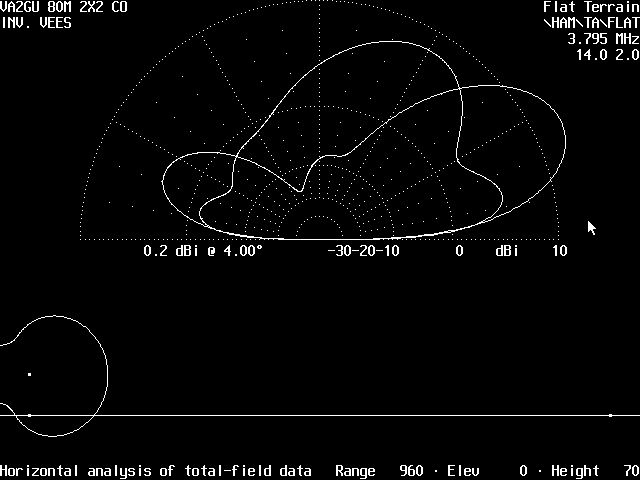
FLAT38NE
MODELED: ACTUAL REALIZED:
South colinear at 0 degree and 1amp current South colinear 1.0amp at 0 degree
North colinear at -140 degrees and 1 amp current. North colinear 0.75amp at -148 degrees
0.2db/4degrees, 7.0db/20 degrees, 10db/43degrees and 7.0db f/b
With slope consolidation running TA program:
MDR38NE
showing gains of:
9.8db/4degrees, 13db/20degrees and 7.8db/42degrees
Again a substantial slope/salt water gains at the lower angles.
Reversing the north and south colinears with the following phases and currents, beaming south west for 3.8mc:
north array at 1.36amp at 0 degree and
south array at 1.0amp at -144 degrees with gains of
1db/4degrees, 7.4db/20 degrees, 10.2db/33.5degrees and 5.4 f/b
With slope consolidation, running TA program:
7.7db/4degrees, 12.4db/20 degrees, 10db/33.5degrees and 8 f/b
The same remarks apply to the SSB patterns and gains as were obtained at CW and benefiting from the slope and sea water proximity.
TOP OF PAGE
The patterns below, show that even with a fair slope to the south west landing in a fresh water lake, the very low 4 degree elevation is no match for a similar slope but landing into 20 miles of sea water. The 4 degree signal is what drives the extremely long distance communication to Japan, China, Indonesia and Alaska long path!
You will note that the gains are quite substantial. But the different topography in the sw direction looses the very low angle elevation gains obtained from 20 miles of sea water to the SE.However, it gets a quite substantial gain of 6db at 4degrees vs a flat terrain reading of -4db at 4 degrees!!!!.
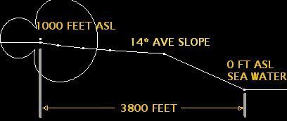
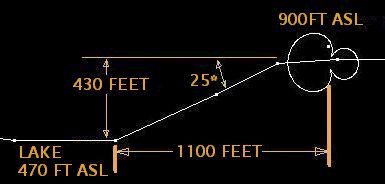
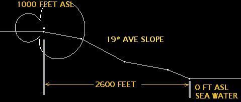
FLAT TERRAIN 14*SLOPE VA2GU NE 25*SLOPE VA2GU SW 19*SLOPE VA2GU SE
1000'high TO SEA LEVEL 1000'high TO 474' LAKE 1000'high TO SEA LEVEL
AT 3800 FEET HORZ. AT 1100' HORZ. AT 2600' HORZ
4*ELEV FOR 0 DB HORZ 10.2DB HORZ 7.7 DB HORZ 11.7DB HORZ
JA/VK LP/SP 1.0DB VERT 8.8DB VERT 7.5 DB VERT 9.7DB VERT
20*ELEV FOR 11 DB HORZ 14.3DB HORZ 11.8 DB HORZ 12.8DB HORZ
UA9/ANTARTICA 5 DB VERT 3.5DB VERT 8.0 DB VERT 3.3DB VERT
40*ELEV FOR 10.5DB HORZ 8.3DB HORZ 9.0DB HORZ 8.0DB HORZ
EUROPE/SOUTH AM 5.0DB VERT 7.3DB VERT 6.3DB VERT 7.3DB VERT
The above gain and phase numbers are quite revealing as to the effects of slopes, the degree of slopes and proximity to salt water as compared to flat terrain.
You will note that "nothing is gained, nothing is lost" in the overall picture. The gains at the very low
angles are obtained at the detriment of the higher elevations.
Moreover, you will note the absence of high (zenith) radiation above 25* to the SE, vs the higher elevation radiation from the colinear array (NE and SW). Thus, the more in phase elements are being added in line towards the desired direction, the greater gain at the lower elevation angles are being produced.
Here the 2 sets of colinear elements produce the same effects as phasing 2 simple dipoles, with the important difference that the colinear will produce greater gains at those elevation angles.
The effects are of removing the high zenith radiation (reducing local qrm), benefiting the lower angles.
On the other hand, the 4 elements beam further reduces the higher angles, adding further gains to the lower angles needed for the long path JA/VK.
CONCLUDING REMARKS:
SEA WATER AND SUITABLE SLOPES ARE THE SECRET TO LOW ANGLES BELOW 20* AND MOSTLY FAVORING HORZ POLAR.
VERT POLAR DOES NOT BENEFIT SO MUCH FROM THE SLOPE AND SEA WATER AS HORZ POLAR DOES.
TOP OF PAGE
MUTUAL COUPLING BETWEEN CLOSE ARRAYS
First, the 2 arrays are at 90 degrees to each other, but interleaved; i.e. i use the DR1 AND DR3 supports of the existing 4el beam to SE, for the SW and SE elements of the new colinear array beaming NE.
Modeling showed the effect caused by the 90* directions of the nested south inverted vee elements started at 3 feet. So i chose to separate those 2 apex by 6 feet.
The north inverted vee elements (NW and NE) are 1/4 wave (70feet) to the north of the SW/SE colinears and thus 1/4w from the center of the 4el beam axis. Modeling there showed negligible effects on the 4el beam.
After erecting/tuning the colinears, the end results measurements showed less than 2% difference on both the phases and currents on the 4el beam from before starting the colinear project, BUT A FAIR VARIATION FROM THE ORIGINAL 4EL SE BEAM DESIGN BEFORE ERECTING THE LOOPS. However more accurate modeling taking into account more accurate ground and geographical conditions (slope, ponds, steel roof buildings, etc), showed that the gain of the 4el beam was not optimal and could be improved.
A new set of L/C values were calculated using the VA2GU ARRAY PHASING.XLS (available for free on my HRLABS.NET page) and put in circuit. In so doing, models showed a gain of almost one db, over original phasing. (....you say all that work for a lousy one db?....well if you ask the question, that means you have never produced anything of gain value on 80m; dbs are very hard to obtain on the lower frequencies, and i'd rather gain one db than lose one db!).
The bandwidth of the 4element beam has been measured from 3740kc to 3840kc and shows less than 1/2 db drop at both ends.
TOP OF PAGE